Bart H. McGuyer
An old puzzle about reciprocity and Tesla coils
TLDR: Tesla coils are reciprocal. However, their equivalent circuits don't have to be, depending on what they model. This can lead to artificially non-reciprocal mutual inductance as predicted way back in 1904.
I remember becoming curious about the typical equivalent circuit for Tesla coils shortly after learning about them. Figure 1 shows this circuit, which makes intuitive sense. However, I wondered where it came from and wanted to understand it better. I looked thoroughly but was unable to find a derivation [1], likely because this is such an old topic that it’s considered “obvious” today.
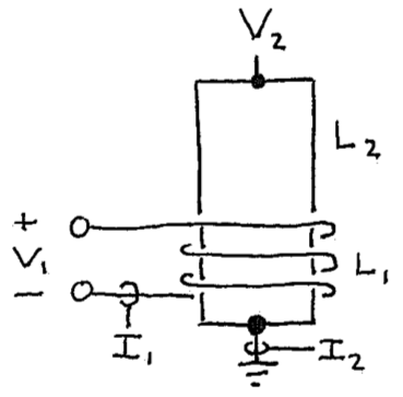
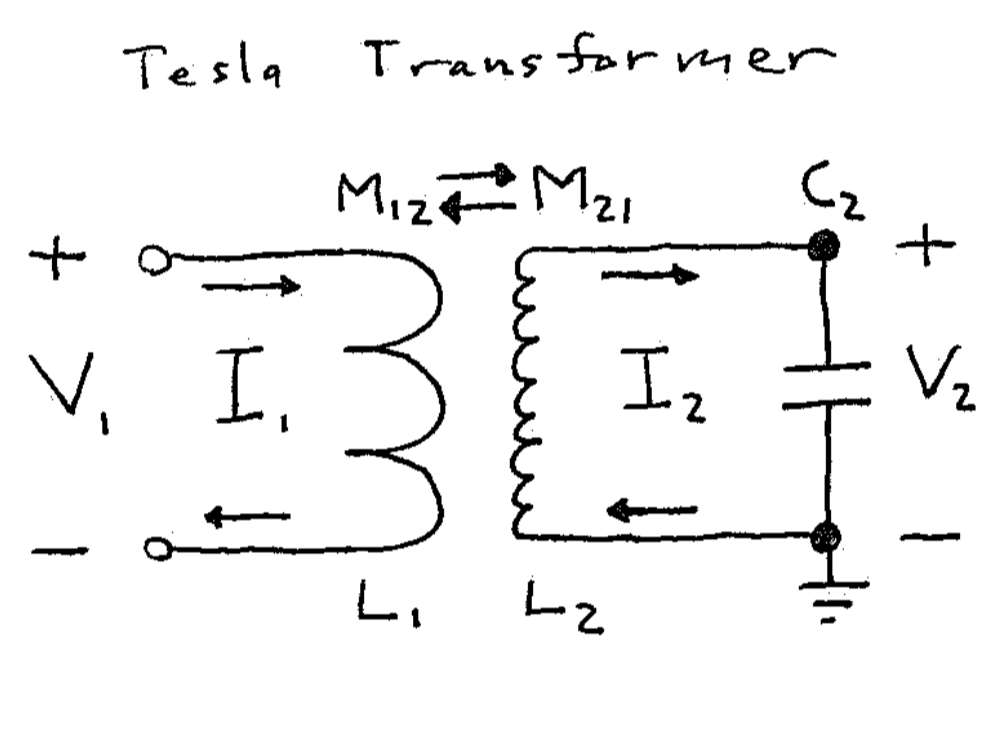
Figure 1: (Left) Sketch of the transformer portion of a Tesla coil with a few-turn inductor often called the primary coil (\(L_1\)) and a single-layer solenoid inductor called the secondary coil (\(L_2\)). Usually there’s an output electrode but it’s been omitted for clarity. (Right) Typical narrow-band equivalent circuit for the physical circuit on the left. The puzzle of interest here is whether or not the mutual inductances \(M_{12}\) and \(M_{21}\) should be equal in this circuit. (Spoiler: They’re definitely equal on the left – see the Neumann formula in a favorite textbook. However, they aren’t always on the right. Yes, I know how that sounds. Read on.)
This topic sat in the back of my mind until I came across the Telegraph equations while reading about Oliver Heaviside [2]. The Telegraph equations provide a way to derive this equivalent circuit if the secondary is approximated as a uniform transmission line, which is good enough for a simple model. I published one approach to do this in [3] and a follow-up pedagogical model expanding on it in [1].
As a result, I can tell you that it’s not “obvious” because if you derive the circuit you’ll run into a problem with reciprocity [3]. You won’t be the first, because this problem turns out to be documented in the scientific literature, though not well known [4]. The original reference seems to be a paper by Paul Drude in 1904 [5], which interestingly is still cited to justify the equivalent circuit for Tesla coils. I was aware of this paper [6] but had not read it (it’s in German and rather long). By a fortunate coincidence, I had asked a friend to translate its beginning and was amazed to learn that it also described this reciprocity issue. Since then, several friends helped make a full English translation that's available in [4].
So, what’s this reciprocity problem? Here’s a quick way to see it (full details are in [3]): To define \(C_2\) and \(L_2\) you’ll need two constraints. For the first constraint the circuit should reproduce the secondary resonant frequency \(w_1\), which requires \(L_2 C_2 = 1/w_1^2\). For the second constraint, it seems reasonable for the circuit to reproduce the output voltage \(V_2\) and base current \(I_2\) of the secondary. After all, Tesla-coil equivalent circuits often include \(V_2\) and \(I_2\) labels [7]. To simplify things, let’s assume there’s no loss and no output terminal or load. Then this requires representing impedance correctly, or \(L_2/C_2 = (V_2/I_2)^2\) in this case. Both the impedance and resonant frequency are measurable, so for a given secondary these constraints can be used to determine \(C_2\) and \(L_2\).
However, that second constraint leads to a puzzling contradiction if you consider the energy stored by the equivalent circuit. Figure 2 shows a thought experiment where the secondary solenoid is artificially lengthened in steps of a full wave. The two constraints we chose still apply in each step for a narrow-band equivalent circuit and the resonances shown, assuming there’s no output terminal or load. Therefore, \(C_2\) and \(L_2\) in the equivalent circuit are the same for each solenoid in the figure. That’s quite strange, because it means that according to the equivalent circuit, the energy stored by each solenoid for a given current \(I_2\) (or voltage \(V_2\)) is identical. Physically, though, this energy can’t be the same, because it must increase with length (each 1/4 wave segment stores the same energy). Therefore, our equivalent circuit contradicts reality, despite being “equivalent” to the actual, physical circuit. Wait, what?
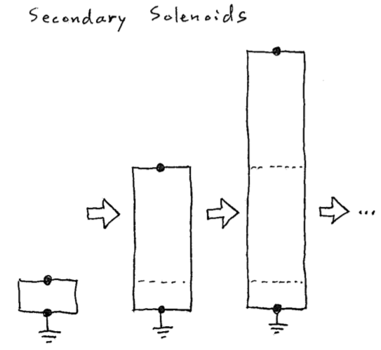
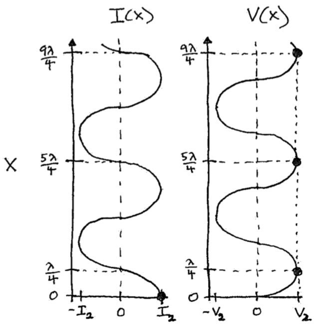
Figure 2: Thought experiment. (Left) Lengthening the secondary coil by full-wave steps preserves the same resonant frequency (as a different mode) and impedance. Therefore, the equivalent circuit is the same for each solenoid length and the energy it represents doesn’t change for a given \(I_2\) or \(V_2\). (Right) Nonuniform spatial profile of the oscillating voltage and current along the solenoid. Each quarter-wave segment stores the same time-averaged energy as every other, so longer solenoids must store more energy.
Before explaining what’s going on here, let’s first connect it to reciprocity and mutual inductance: If the transformer in Figure 1 is reciprocal, then energy is neither lost or gained when it transfers between the primary and secondary via magnetic coupling. The same is true for the equivalent circuit in Figure 1 if the mutual inductances are equal, \(M_{12} = M_{21}\). However, we’ve just argued above that the secondary portion of the circuit misrepresents energy. Assuming the primary portion represents energy correctly (it represents a lumped inductor), the circuit can’t be reciprocal, so \(M_{12} \neq M_{21}\) in Figure 1.
What’s going on here is that we’re trying to use a lumped-element model (the equivalent circuit) to represent a distributed system (the secondary, approximated as a transmission line) that has more degrees of freedom. This feels safe because it’s customary for Tesla coils, but it’s not here. As a result, the equivalent circuit, or really, its circuit parameters aren’t unique: We chose to model the voltage \(V_2\) and current \(I_2\), so the circuit misrepresents energy and has to be nonreciprocal. You could choose instead to model energy, making the circuit reciprocal, but then it’d misrepresent \(V_2\), \(I_2\), or both. What the circuit can’t do is model \(V_2\), \(I_2\), and energy all together, at least, for this special case.
One fun interpretation of the circuit that models \(V_2\) and \(I_2\) is to note that the “lumped” parameters \(C_2\) and \(L_2\) are still distributed [3]. That is, like transmission-line parameters that are distributed per length, these parameters are distributed per angular length (i.e., per \(\pi/2\) radians) of the solenoid. In this interpretation, \(C_2\) and \(L_2\) wouldn’t be expected to scale with the solenoid length in Figure 2. The equivalent circuit then misrepresents energy because it correctly represents energy stored per angular length, which again doesn’t scale with the solenoid length. Thus, its mutual inductance has to be nonreciprocal to convert between the different units used to represent energy in the primary and secondary portions of the circuit (i.e., between real energy and energy per radian).
For much more detail and some history, please see [3] and [4]. Note that the model in [3] is only a rough approximation so shouldn’t be expected to capture real solenoids, which are much more complicated than uniform transmission lines. Also, in practice, Tesla coils usually have output terminals (conveniently omitted in Figure 1) that capacitively load the secondary. With some effort, one can show that adding this load shrinks the nonreciprocity.
Nevertheless, Tesla coil enthusiasts seem to have run into this puzzle through more accurate numerical simulations: There’s an online effort to model Tesla coils called the Tesla Secondary Simulation Project (TSSP) [8] that contributed to a popular Tesla coil design tool [9], which curiously reports a few different \(L_2\) and \(C_2\) values for any modeled secondary. This seems to be the non-uniqueness we encountered above: The TSSP documentation says these different values are needed to model different things, namely energy (TSSP “equivalent energy storage” \(L_{ee}\) and \(C_{ee}\)) and impedance (TSSP “equivalent series” \(L_{es}\) and \(C_{es}\)).
Today, it's customary to contrain most equivalent circuits for similar distributed systems (e.g., microwave networks) to represent energy correctly [3], so this interesting puzzle is avoided. One exception, again related to Tesla coils, is that it's still common to constrain equivalent circuits for single-layer solenoid inductors to use the DC self-inductance of the solenoid so that the effective solenoid self-capacitance can be estimated with an old empirical formula (the "Medhurst" formula). Otherwise, the old puzzle described above seems to just be a fun curiosity without much importance today.
References- [1] If you know of one, please feel free to share. For my attempt, please see the technical note "Deriving the equivalent circuit of a Tesla coil" (PDF).
- [2] Book: “Oliver Heaviside: The Life, Work, and Times of an Electrical Genius of the Victorian Age” by Paul J. Nahin (Johns Hopkins, 1988).
- [3] Article (free to read): B. McGuyer, “Paul Drude’s Prediction of Nonreciprocal Mutual Inductance for Tesla transformers,” PLoS ONE 9: e115397 (2014).
- [4] Article (free to read): J. Sederberg, J. Burkhart, F. Apfelbeck, and B. H. McGuyer, “Translation of an Article by Paul Drude in 1904”, arXiv:1303.1588v2 [physics.hist-ph] (2015).
- [5] Drude’s article from 1904: P. Drude, Annalen der Physik 13, 512 (1904).
- [6] I knew of this partial translation shared by Tesla coilers: http: //www.coe.ufrj.br/~acmq/drude/project.html
- [7] For example: K. D. Skeldon, A. I. Grant, and S. A. Scott, American Journal of Physics 65, 744 (1997).
- [8] Tesla Secondary Simulation Project (TSSP): http://abelian.org/tssp/
- [9] JavaTC: http://www.classictesla.com/java/javatc/javatc.html
(May 2018; updated November 2020)
© , bartmcguyer.com